
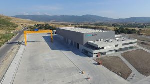
Mekanik sistem Elevate 1,14 mm UltraPly TPO uygulaması Yalkon Mühendislik tarafından başarıyla tamamlanmıştır.
Elevate TPO Mechanically Attached Roofing System
The specifications herein described are general guidelines created from information provided to Elevate Building Products by project specifiers and design professionals. They are intended to facilitate and assist in the selection of roof materials, not as a substitute for the judgment of a design professional. The ultimate selection of a specification for a particular roof remains the responsibility of the building owner and their design professionals.
When a Green Roof and/or Photovoltaic System will be installed on top of this Elevate TPO Roofing System, we refer to our specifications for TPO Roofing Systems for Extensive/Semi-Intensive Green Roofs and/or Enviro-Ready Roofing Systems.
1 Preparation of the Substrate
1.1 New Roof
1.1.1 General
Roof slope should be a minimum of 2% to allow for adequate drainage of the roof taking into account the deflection of the roof.
The roof surface will be made clean, dry, smooth and free of contaminants such as grease, animal fats, coal tar and oil based products. All sharp edges, fins and rough surfaces that could damage the membrane will be removed or if they can’t be removed, isolated from the membrane with a leveling layer.
It is essential that the roof structure is capable of supporting the imposed load of the new roofing system. When necessary, the advice of a Structural Engineer should be sought in this respect.
1.1.2 Substrate Type: Metal Decking
Metal decks require a minimum thickness of 0.75 mm for galvanized steel. Deck should be installed without inducing stresses (over-stretching/compressing) that could cause the flutes to bend. The deck should be fixed to the substrate using sufficient fasteners as per the manufacturer’s specifications.
1.1.3 Substrate Type: Wooden Decks
The deck needs to consist of wooden boards with a minimum thickness of 18 mm. Thickness of the boards depends on the distance between the purlins. Wooden panels should be kept dry before and during the waterproofing works.
1.1.4 Substrate Type: Concrete
Concrete needs to be structurally sound and dry to the touch. Concrete should have aged for a minimum of 2 weeks before starting any roofing works.
1.2 Reroofing
1.2.1 General
Roof slope should be a minimum of 2% to allow for adequate drainage of the roof taking into account the deflection of the roof.
All outlets must be protected to prevent debris entering and causing blockage of down pipes.
The roof surface will be made clean, dry, smooth and free of contaminants such as grease, animal fats, coal tar and oil based products. All sharp edges, fins and rough surfaces that could damage the membrane will be removed or if they can’t be removed, isolated from the membrane with a leveling layer.
It is essential that the existing roof structure is capable of supporting the imposed load of the new roofing system. When necessary, the advice of a Structural Engineer should be sought in this respect.
1.2.2 Substrate Type: Metal Decking
Metal decks require a minimum thickness of 0.75 mm for galvanized steel. Metal decks will be inspected for their deflection and assessed for their pullout resistance.
1.2.3 Substrate Type: Wooden Decks
The deck needs to consist of wooden boards with a minimum thickness of 18 mm. Thickness of the boards depends on the distance between the purlins. Wooden decks will be fully examined for their quality (dryness) and pullout resistance. Any wet or unsound portions will be replaced with new material prior to the installation of the membrane system.
1.2.4 Substrate Type: Concrete
Concrete needs to be structurally sound and dry.
1.2.5 Existing Membrane: Smooth Bitumen
All debris and non-adherent areas of the existing bitumen roof finish will be removed. Blisters and buckles will be cut open and sealed, defects will be repaired by gentle warming and redressing.
1.2.6 Existing Membrane: Granule Surfaced Bitumen
All chippings, debris and non-adherent areas of the existing bitumen roof finish will be removed from the surface. Blisters and buckles will be cut open and sealed, defects will be repaired by gentle warming and redressing.
A separation layer of geotextile (min. 200 gr/m²) or an insulation board or a half-inch (12.7 mm) thick Elevate ISOGARDTM HD Cover Board or equivalent will be installed prior to the installation of the roofing membrane.
1.2.7 Existing Membrane: Thermoplastic Membrane
The existing thermoplastic membrane will be cut at the perimeter and all flashings will be removed from the upstands and penetrations. When necessary, the membrane will be cut at equidistant intervals to release the tension out of the membrane.
A separation layer of geotextile (min. 200 gr/m²) or an insulation board or a half-inch (12.7 mm) thick Elevate ISOGARDTM HD Cover Board or equivalent will be installed prior to the installation of the roofing membrane.
1.2.8 Existing Membrane: EPDM Membrane
All debris will be removed from the existing roof surface. All non-adherent parts of the existing EPDM membrane at upstands and penetrations will be removed.
2 Vapour Control Layer
2.1 General
The necessity, type and thickness of the vapour control layer need to be determined based upon the designation of the building and the regional climatic conditions.
All installations need to be in accordance with the recommendations of the manufacturer and the method of fixation needs to be adapted to both the substrate and the roofing system to be installed.
Dress to provide sufficient edge protection to new thermal insulation at perimeter, abutments and details etc.
3 Insulation & Cover Board
3.1 General
The thermal resistance of the total package of insulation and cover boards requires minimum R-value of … m²K/W (check your local and/or National Standards).
3.2 Insulation Type
3.2.1 Mineral Wool (MW)
Mineral wool boards have a minimum compressive strength of 40 kPa; UEAtc class C.
3.2.2 Perlite (EPB)
Perlite boards have a minimum compressive strength of 200 kPa.
3.2.3 Polyurethane (PUR)
Polyurethane boards have a minimum compressive strength of 120 kPa with an acceptable facer.
3.2.4 Polyisocyanurate (PIR)
Polyisocyanurate boards have a minimum compressive strength of 120 kPa with an acceptable facer.
3.2.4.1 Elevate ISO 95+ GL
Manufacturer needs to be ISO 9001:2008 and ISO 14001:2004 certified. The foam technology does not contribute to the depletion of the earth’s ozone layer (zero ODP) and uses a HCFC-free blowing agent.
The polyisocyanurate insulation boards consist of closed-cell polyiso foam core laminated on both sides to a black glass reinforced mat facer of app. 150 g/m². The boards will comply with the following characteristics when tested in accordance with EN 13165:
– Dimensions: 1.22 m x 2.25 m
– Thickness: from 25.4 mm to 101.6 mm
– Compressive strength: >= 138 kPa
– Thermal conductivity: <= 0.029 W/mK
Keep insulation dry at all times. Do not install over wet, damp or uneven substrates.
The insulation boards comply to following certifications, but not limited to: CE marked according to EN 13165, ASTM C1289 Type II Class 1, UL Classified, FM Class 1 Approved.
3.2.4.2 Elevate RESISTA AK
Manufacturer needs to be ISO 9001:2008 certified. The foam technology does not contribute to the depletion of the earth’s ozone layer (zero ODP) and uses a HCFC-free blowing agent.
Elevate polyisocyanurate insulation boards consist of closed-cell polyiso foam core laminated on both sides to a gastight multi-layered aluminium complex. The boards will comply with the following characteristics when tested in accordance with EN 13165:
– Dimensions: 1.2 m x 0.6 m,
1.2 m x 1.2 m,
1.2 m x 2.4 m
– Thickness: from 30 mm to 140 mm
– Compressive strength: >= 150 kPa
– Thermal conductivity: <= 0.023 W/mK
– Reaction to fire: E
Keep insulation dry at all times. Do not install over wet, damp or uneven substrates.
The insulation boards comply to following certifications, but not limited to: CE marked according to EN 13165, ACERMI, FM Class 1 Approved.
3.2.5 Expanded polystyrene (EPS)
Expanded polystyrene boards have a minimum compressive strength of 120 kPa.
Direct contact between polystyrene boards and contact adhesives and/or primers must be avoided.
3.3 Cover Board Types
3.3.1 ISOGARD HD
Manufacturer needs to be ISO 9001:2008 and ISO 14001:2004 certified. The foam technology does not contribute to the depletion of the earth’s ozone layer (zero ODP) and uses a HCFC-free blowing agent.
Elevate ISOGARD HD is a high-density, closed-cell, polyisocyanurate board with a coated fiberglass facer on both sides designed for use as a cover board. The boards will comply with the following characteristics when tested in accordance with EN tests:
– Dimensions: 1.22 m x 2.25 m
– Thickness: 12.7 mm
– Weight: 1.8 kg/m²
– Compressive strength: >= 800 kPa
Keep cover board dry at all times. Before board is placed on the roof deck, the surface must be clean, dry, free of debris, water, ice or snow and suitably prepared.
3.3.2 DensDeck Roof Board
DensDeck Roof Board exists of a high-density gypsum core, bonded on front and back with fiberglass mats. The boards provide an excellent fire barrier, wind-uplift properties, flute spanning that stiffens and provides increased foot traffic resistance to the roof deck. The boards will comply with the following characteristics:
– Dimensions: 1.22 m x 2.44 m
– Thickness: 6.4 mm, 12.7 mm, 15.9 mm
– Weight: 5.9 kg/m², 9,8 kg/m², 12.2 kg/m²
Keep cover board dry at all times. Before board is placed on the roof deck, the surface must be clean, dry, free of debris, water, ice or snow and suitably prepared.
3.4 Insulation Attachment and/or Cover Boards
3.4.1 Thermal insulation and/or Cover Boards mechanically attached
Install the boards on above underlay with end joints staggered. When installing two layers of boards, ensure that the joints of both layers do not coincide. Mechanically fix to pattern and frequency advised by manufacturer, all in accordance with national wind uplift standards. Install fully in accordance with manufacturers instructions. Use Elevate insulation plates and fasteners or equivalent.
Install in any one day only as much boards as can be protected by the completed roofing system that same day.
3.4.2 Thermal insulation and/or Cover Boards adhered
Install the boards on above underlay with end joints staggered. When installing two layers of boards, ensure that the joints of both layers do not coincide.
Adhere the boards using Elevate Twin Pack Insulation Adhesive or an equivalent adhesive system, according a pattern as advised and approved by manufacturer, all in accordance with national wind uplift standards.
Elevate insulation boards shall not be larger than 1.2 m x 1.2m. Install fully in accordance with manufacturers instructions.
Install in any one day only as much boards as can be protected by the completed roofing system that same day.
4 Elevate TPO Roofing Membrane
TPO Membranes and accessories need to be supplied from the same manufacturer. Manufacturer needs to be ISO 9001:2008 and ISO 14001:2004 certified.
4.1.1 Roofing membrane: Elevate UltraPlyTM TPO membrane 1.2 mm (0.047”)
The Elevate UltraPly TPO membrane is a flexible thermoplastic polyolefin (FPO) roofing membrane made from the incorporation of an ethylene propylene rubber into a polypropylene matrix and produced with a polyester weft-inserted reinforcement. The membrane can be supplied in the following dimensions and colors:
– Thickness: .047″ (1.2 mm);
– Weight: 1.235 kg/m²;
– Length: 30.50 m;
– Width: 1.00 m; 1.50 m; 2.00 m;
– Color: white; gray;
Dimension of the membrane will be chosen in view of the dimensions, complexity of the roof and in function of a wind uplift calculation as determined by national standards.
The membrane complies with the following characteristics when tested in accordance with EN 13956:
– Tensile strength (L/T): >= 800 N/50 mm
– Elongation at break: >= 20 %
– Tear Resistance (L/T): >= 400 N
– Static loading: >= 20 kg (on soft and hard support)
– Resistance to impact: >= 2000 mm (on soft support)
>= 500 mm (on hard support)
– Joint peel resistance: >= 300 N/50mm
– Joint shear resistance: >= 800 N/50mm
– Cold foldability: <= -40 °C
– Durability/UV-exposure: Pass EN 1297 (>7500h)
– Solar Reflectance Index (initial/3 years):
98/81 (for white membrane)
The membrane has been assessed for its properties according to EN 13956 (CE mark), ASTM D-6878, DIN V 20000-201, is FM approved and carries following certificates, but not limited to: ETA, ATG, KOMO, ETN, Atex.
Various BROOF(t1, t3) classified build-ups using the membrane are available.
4.1.2 Roofing membrane: Elevate UltraPlyTM TPO membrane 1.5 mm (0.059”)
The Elevate UltraPly TPO membrane is a flexible thermoplastic polyolefin (FPO) roofing membrane made from the incorporation of an ethylene propylene rubber into a polypropylene matrix and produced with a polyester weft-inserted reinforcement. The membrane can be supplied in the following dimensions and colors:
– Thickness: .059″ (1.5 mm);
– Weight: 1.525 kg/m²;
– Length: 30.50 m;
– Width: 1.00 m; 1.50 m; 2.00 m; 3.05 m;
– Color: white; gray;
Dimension of the membrane will be chosen in view of the dimensions, complexity of the roof and in function of a wind uplift calculation as determined by national standards.
The membrane complies with the following characteristics when tested in accordance with EN 13956:
– Tensile strength (L/T): >= 1200 N/50 mm
– Elongation at break: >= 20 %
– Tear Resistance (L/T): >= 400 N
– Static loading: >= 20 kg (on soft and hard support)
– Resistance to impact: >= 2000 mm (on soft support)
>= 800 mm (on hard support)
– Joint peel resistance: >= 300 N/50mm
– Joint shear resistance: >= 800 N/50mm
– Cold foldability: <= -40 °C
– Durability/UV-exposure: Pass EN 1297 (>7500h)
– Solar Reflectance Index (initial/3 years):
98/81 (for white membrane)
The membrane has been assessed for its properties according to EN 13956 (CE mark), ASTM D-6878, DIN V 20000-201, is FM approved and carries following certificates, but not limited to: ETA, ATG, KOMO, ETN, Atex.
Various BROOF(t1, t3) classified build-ups using the membrane are available.
4.1.3 Roofing membrane: Elevate UltraPlyTM TPO membrane 1.8 mm (0.071”)
The Elevate UltraPly TPO membrane is a flexible thermoplastic polyolefin (FPO) roofing membrane made from the incorporation of an ethylene propylene rubber into a polypropylene matrix and produced with a polyester weft-inserted reinforcement. The membrane can be supplied in the following dimensions and colors:
– Thickness: .071″ (1.8 mm);
– Weight: 1.815 kg/m²;
– Length: 30.50 m;
– Width: 1.00 m; 1.50 m; 2.00 m;
– Color: white; gray;
Dimension of the membrane will be chosen in view of the dimensions, complexity of the roof and in function of a wind uplift calculation as determined by national standards.
The membrane complies with the following characteristics when tested in accordance with EN 13956:
– Tensile strength (L/T): >= 1200 N/50 mm
– Elongation at break: >= 20 %
– Tear Resistance (L/T): >= 400 N
– Static loading: >= 20 kg (on soft and hard support)
– Resistance to impact: >= 2000 mm (on soft support)
>= 1000 mm (on hard support)
– Joint peel resistance: >= 300 N/50mm
– Joint shear resistance: >= 800 N/50mm
– Cold foldability: <= -35 °C
– Durability/UV-exposure: Pass EN 1297 (>7500h)
– Solar Reflectance Index (initial/3 years):
98/81 (for white membrane)
The membrane has been assessed for its properties according to EN 13956 (CE mark), ASTM D-6878, DIN V 20000-201, is FM approved and carries following certificates, but not limited to: ETA, ATG, KOMO, ETN, Atex.
Various BROOF(t1, t3) classified build-ups using the membrane are available.
Ponding water, snow, frost and/or ice present in more than trace amounts, must be removed from the work surface prior to installing the system.
4.2.1 Mechanically Attached System (in seam)
The TPO strips are mechanically attached to the substrate using Elevate HD Seam Plates and fasteners or approved plates and fasteners. The plates need to be positioned at least 20 mm in from the edge of the membrane.
In case of doubt about the selected fastening system and/or the quality of the support, pullout tests need to be conducted on site to determine the actual pullout values of the fasteners applied. Test areas shall include corner and perimeter zones.
The width of the TPO strips and/or the spacing of the plates and fasteners must be calculated strictly in accordance with local standards. A layout plan shall be provided upon request.
Install the Elevate UltraPly TPO single-ply roofing membrane loose laid on a suitable substrate as close to its final position as possible, and allow to relax a minimum of 30 minutes before attachment or splicing. Adjoining sheets are overlapped at least 150 mm in case of a seam with mechanical anchoring and 75mm in case of a seam without mechanical anchoring. Layout the Elevate UltraPly TPO membranes in a fashion so that field and flashing seams are installed to shed water. Orient the TPO sheets so that any exposed (cut) edges of a sheet are used as the bottom sheet in splices whenever possible.
As an alternative to the mechanical anchoring in the seam the TPO membrane panels can be mechanically attached on top of the membrane. These mechanical attachments are covered using a pre-cut TPO 8″ Reinforced Cover Strip or a separate TPO strip.
All TPO strips are heat-welded to form a continuous, watertight membrane (see § 4.3.1).
4.2.2 Mechanically Attached System (induction)
The approved insulation boards are mechanically attached to the substrate using approved fasteners and TPO coated insulation plates. The fixing pattern must be calculated strictly in accordance with local standards. A layout plan shall be provided upon request.
In case of doubt about the selected fastening system and/or the quality of the support, pullout tests need to be conducted on site to determine the actual pullout values of the fasteners applied. Test areas shall include corner and perimeter zones.
Install the Elevate UltraPly TPO single-ply roofing membrane loose laid over the fixed insulation boards. Adjoining sheets are overlapped at least 75mm. Layout the Elevate UltraPly TPO membranes in a fashion so that field and flashing seams are installed to shed water. Orient the TPO sheets so that any exposed (cut) edges of a sheet are used as the bottom sheet in splices whenever possible.
All TPO strips are heat-welded to form a continuous, watertight membrane (see § 4.3.1).
The UltraPly TPO roofing membranes are welded onto the underlying TPO coated plates using an approved induction welding tool, according to its manufacturer’s guidelines. When the induction welding cycle is complete, a magnetic cooling clamp is immediately placed over the welded UltraPly TPO membrane and plate assembly for at least one minute.
All splices need to be hot air welded.
Set-up of the welding equipment is the responsibility of the installer. The air intake, temperature and speed of the machine must be adjusted to provide proper seam strength.
Seams made with an automatic welder must be a minimum of 38 mm wide. Seams made with hand welders must be a minimum of 50 mm wide. The weld shall be executed and pressured with a pressure roller.
Any visible cut edges with scrim exposed shall be covered with UltraPly TPO Cut Edge Sealant or TPO General Purpose Sealant.
4.3.2 Base Tie-in
At all changes in angles greater than 15%, the membrane must be restrained using one of the approved ‘Base Tie-in’ methods as per the Elevate specifications.
4.3.2.1 Detail 1: Base Tie-in with Fasteners and Plates
The TPO membrane should be mechanical attached with Elevate HD Seam Plates, Metal Batten Bars or a TPO Coated Metal strip and fasteners or other approved plates and fasteners as close as possible at the angle change, max. every 300 mm o.c. The TPO membrane must extend 15 mm beyond the edge of the plates.
Plates and fasteners are either installed on the flat roof substrate or on the wall. The selection for vertical or horizontal attachment is related to the ease of application (thickness of insulation and nature of the substrate).
4.3.2.2 Detail 2: Base Tie-in with UltraPly TPO Coated Metal
Mechanical fasten the UltraPly TPO Coated Metal to the supporting structure using appropriate fasteners, all according the Elevate guidelines. Position the fasteners not closer than 15 mm from the metal edge.
Heat weld the field TPO membranes to the TPO Coated Metal flashing. Seams must meet requirements mentioned in § 4.3.1.
4.3.3 Vertical flashings roof edges and penetrations
Vertical facings are either flashed with the Elevate UltraPly TPO Coated Metal or with a separate strip of UltraPly TPO membrane which is fully adhered with Bonding Adhesive and/or mechanically attached, all according the Elevate Technical Guidelines. If necessary, install a suitable overlayment (e.g. a half-inch (12.7 mm) thick Elevate ISOGARDTM HD Cover Board or equivalent) to ensure the adherence of the TPO membranes.
The required height for the TPO flashing should be determined by local regulations. Do not flash over existing through-wall flashings, weep holes and overflow scuppers.
On top of the upstands, the TPO membrane or TPO Coated Metal is mechanically attached and finished with an applicable detail (see further).
All corners should be finished using the UltraPly TPO Pre-molded Corners (inside or outside) or field fabricated corners from UltraPly TPO Unsupported Flashing.
The corners are heat welded into place according the Elevate Technical Guidelines.
4.3.5.1 Termination Bar Detail.
The TPO membrane will be secured with a Elevate Termination Bar, used in conjunction with Elevate water repellent sealant Water Block between the membrane and the substrate under compression behind the termination bar. The termination bar must be installed directly into the wall surface and mechanically fixed at maximum 200 mm centers using appropriate fasteners. A bead of Elevate General Purpose Sealant is applied along the top edge of the termination bar.
4.3.5.2 Counterflashing Detail
The TPO membrane will be mechanically fastened with a metal batten strip. A bead of Elevate General Purpose Sealant is applied along the top edge of the TPO membrane. A separate metal counterflashing is secured to the vertical face above the membrane termination. The counterflashing will cover the top of the fastening system by a minimum of 100 mm.
4.3.6.1 Metal Coping Terminations
The membrane shall be returned over the upstand and secured to the horizontal surface of the parapet. If necessary, a suitable timber plate will be installed, mechanically fixed to the top of the parapet to provide an even substrate. The metal coping will be installed, ensuring full protection of the top of the upstand detail.
4.3.6.2 Concrete Coping Terminations
The membrane will be stopped at sufficient distance of the wall edge so as to allow a good adhesion of the mortar to the wall without compromising the watertightness of the detail. The coping stone will be installed, ensuring full protection of the top of the upstand detail.
Allow the TPO membrane to pass over the edge sufficiently. If necessary, install a wood nailer at the roof edge to provide a suitable edge detail. Install the appropriate metal edge profile fastened to roof edge at maximum 100 mm on centre, using appropriate fasteners. The horizontal flange of the metal profile and the TPO membrane shall be prepared with Single-Ply Prime and flashed using Elevate self-adhesive UltraPly TPO QuickSeam Flashing. Ensure an adequate overlap of 75 mm beyond the inner edge of the profile.
4.3.6.4 Metal Roof Edge from UltraPly TPO Coated Metal
Allow the TPO membrane to pass over the edge sufficiently. If necessary, install a wood nailer at the roof edge to provide a suitable edge detail. Install the metal edge profile, fabricated from TPO Coated Metal, fastened to roof edge at maximum 100 mm on centre, using appropriate fasteners. Weld the TPO membrane onto the TPO Coated Metal.
4.3.7.1 General
All pipes must be anchored to the deck. Metal edges used at pipe penetrations must have rounded corners.
All TPO components should be protected from direct contact with steam or heat sources when the in-service temperature of the penetration is in excess of 60 °C. In such cases the flashing can be installed directly to an intermediate insulated cool sleeve.
All penetrations must allow flashing terminations of a minimum height determined by local regulations.
4.3.7.2 Pre-molded Pipe Flashing
Pipe penetrations accessible from the top side and with a maximum diameter of 203 mm, can be flashed in using Elevate UltraPly TPO Pipe Flashing. Heat weld the boot to the surrounding TPO membrane around the base of the penetration and secure on top using a stainless steel clamping ring. Finish by applying a bead of General Purpose Sealant around the entire circumference of the Pipe.
4.3.7.3 Field Fabricated Pipe Flashing
Field fabricated flashing of pipes is to be executed using UltraPly TPO Unsupported Flashing, in accordance with the Elevate Technical Guidelines. This method is to be used where the top of the pipe is not accessible and/or the pipes are larger than 203 mm in diameter. The UltraPly TPO Unsupported Flashing is secured on top using a stainless steel clamping ring. Finish by applying a bead of General Purpose Sealant around the entire circumference of the Pipe.
4.3.7.4 Pipe Clusters and Unusual Shaped Penetrations
Install pre-fabricated penetration pockets around the penetrations. Up to a pipe diameter or cluster of 90 mm a pre-molded UltraPly TPO Penetration Pocket can be used, for larger openings a pocket can be made out of TPO Coated Metal. Fill the penetration pockets with Elevate Pourable Sealant, so as to shed water. The Pourable Sealant shall be a minimum of 50 mm deep, use filler as required. All installed in accordance with the Elevate Technical Guidelines.
Number and dimensions of the outlets are in accordance with national regulations.
4.3.8.1 Rainwater Outlets incorporating a Clamping Ring
Install roof outlets, providing a clean even finish on the mating surfaces between the clamping ring and the drain bowl.
Position the TPO membrane, and then cut a hole for the outlet to allow 10 to 20 mm of membrane to extend inside the clamping ring past the drain bolts. Install Elevate water repellent sealant Water Block beneath the membrane, where the clamping ring seats. Install the outlet clamping ring and clamping bolts. Tighten the clamping bolts to achieve constant compression and install gravel/leaves guard.
4.3.8.2 Rainwater Outlet/Scupper incorporating an Insert Piece
The TPO membrane sheet must be in place prior to installation of the insert piece. Cut a hole to the size of the insert piece, over the centre of the outlet.
Install a pre-fabricated or pre-molded compatible TPO drain insert piece and weld it to the field TPO membrane. The drain insert flanges, or the TPO membrane around it, shall be fastened using Elevate HD Seam Plates and Fasteners or an appropriate fastening system.
Heat weld a piece of UltraPly TPO membrane or UltraPly TPO Unsupported Flashing to the flange and onto the field membrane, covering the fasteners.
The membrane is mechanically attached at both sides of the expansion joint using Elevate HD Seam Plates and Fasteners or an appropriate fastening system, maximum 300 mm on centre. A compressible tube is added to allow for excess membrane. The expansion joint is then covered with a reinforced UltraPly TPO cover piece onto the TPO membrane. Ensure there is enough excess membrane to accommodate building movement.
4.3.10 Walkway Pads
Walkways shall be installed in specific areas such as access points to the roof (doorways, ladders, …) and on roof parts subjected to traffic more frequent than once per month.
The installation of concrete pavers is not acceptable.
4.3.10.1 UltraPly TPO Walkway Pads
Prior to heat weld the UltraPly TPO Walkway Pad (white) to the TPO membrane with textured side up. The TPO membrane needs to be clean and free of dirt, dust and debris. Install the Elevate UltraPly TPO Walkway Pads as per Elevate specifications.
The Elevate Building Products specifications will be strictly followed for all products supplied by the company. Prior to installation, Elevate Building Products must approve any deviation from the specifications. The works shall only be installed by an authorized contractor. A Elevate approved Contractor Certificate with validity date shall be provided before start of the works.
Installations must comply with all current relevant standards, codes of practice, and the Building Regulations.
A Elevate standard 10 years warranty shall be issued to the building owner on completion.
All materials shall be stored clear of ground and moisture with weather protective covering. Keep all adhesives, sealants and primers away from sources of ignition.
Do not apply roofing membrane during inclement weather or when ambient conditions will not allow proper application.
At the end of the working day: Temporarily seal the membrane to the deck to prevent any water infiltration. Temporary closures that ensure that moisture does not damage any completed section of the new roofing system are the responsibility of the roofing contractor. Completion of flashings, terminations and temporary closures shall be completed as required to provide a watertight condition. Ensure protection of warm deck insulation by temporary seal. Ensure that the sequence of laying enables temporary sealing of loose membrane edges to be down the slope and not against the flow of water. On resumption of work cut away the tail of the membrane from completed area and remove from roof.
Adequate temporary protection must be provided over the installed membrane during the works program, particularly at temporary walkways, access points to the roof, roofing material stockpiles etc. in order to prevent damage.
Safety scaffolding, rubbish skips, access ladders etc. should be agreed with the client and in accordance with the current Health and Safety regulations.
The main contractor shall ensure that all areas of the finished roofing system shall be protected from roofing related work traffic and other trades until completion of all works.
About The Author
admin